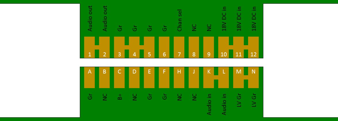
Pin-out for the edge connector?

Synergy/MTS Forum

Help Support Synergy/MTS Forum:

This site may earn a commission from merchant affiliate links, including eBay, Amazon, and others.

goldtop

Member
Joined
Apr 9, 2015
Messages
18
Reaction score
0
Location
Cambridge, England
Hi all, newbie here, having just picked up an RM100C with 4 modules (Deluxe, Plexi, XTC, UltraXL). It was a steal (at far less than the cost of the 4 modules alone). I'd always wondered about the MTS amps but never tried one.

Anyhoo, a big part of the appeal are the modular construction and modding potential allows so many possibilities. I've had a look at some of the mods and they all look and sound very appealing.

For my own approach, though, I'd first like to find out the pin-out of the edge connector. Anyone have it?

(I did a search and then found a posting that had some strange CAPCAD drawings/schematics but don't have the software to open those.)
 
Not a busy forum, or those that have worked it all out are keeping the info to themselves? :D

No worries, I'll get the spare module out, trace some tracks and try to reverse engineer it.

(Of course, if the info is here and I've overlooked it while going through the DIY area, please point me in the right direction!)
 
Well, they say that the first sign of madness is talking to yourself, but I don't care. :)

Managed to find the edge connector detail on a schematic, the latter being linked to from this site. The actual link was broken, but a quick search and I see that some kind MTS soul has put it on his Dropbox: https://dl.dropboxusercontent.com/u/3602793/SL_1.pdf

So that's a head start on sussing out the edge connector. I'll investigate further and draw it up and post it here ASAP.
 
Wellllllllll, you could be a figment of my imagination... Do you mind if I call you Harvey? ;)

Anyhoo, here's my first draft:

XBglKoo.jpg


This shows the module's edge connector's two sides (with the underside shown as if you are looking at the bottom metal plate).

If anyone can check/contradict/etc, I'll delete and update the image.

And if anyone knows the name of this type of edge connector, that'd be very useful - I can order in some matching parts.

TIA
 
:)

So I also want to get a feel for the specs for the various supplies/signals on the edge connector.

[EDIT: from the 18V DC supply] It seems pretty universal in these modules that there's two 12AX7s and just a few H11F1s, transistors and LEDs to supply. So I'd estimate that each module pulls 320-350mA or so.

For the HV, I see 320V DC marked on the various schematics here, and for two preamp valves, I guess we pull well under 10mA, and probably half that. Wonder if that's fused? In any case, it's trivial compared to the HV current supplied to the RM100's power valves.

So each module pulls perhaps 5-7W.

If anyone has a schematicc of the RM100's main power supply board, that'd be very useful for delving further! (Hint)
 
Power dissipation will be entirely dominated by the heaters: 6.3V x 300mA = 2W. Cold current will be higher thg :!:

four triodes: 4mA
some low voltage logic stuff: 20mA max.

I dont think the induvidual modules have, or are, fuse protected. But I would expect the HV and Heater current to be fuse protected.

I think my HV for the modules was closer to 350V. It depends offcourse on the number of modules inserted. One of the cement HV drop resistors was faulty in mine. I have only a replacement for halve the value, so my HV is a bit higher still.
 
Thanks for broadly confirming the details. I calc 3.6W for the pair of valves' heaters.

As far as I can see no module has anything other than 12AX7 valves, and even the low-gain "clean" modules still have two of them. :)
 
I'm currently building a two module bass amp for Egnater/MTS modules, so I've recently been popping in here lately (just joined today).

Your pin-out looks right to me, I'd just like to add:
pins 3,4,5,6,E,F are the module's signal ground plane
pins M,N are the modules heater ground for the module's 12V Vreg
pin A is HT ground
pin 10 is filtered but unregulated DC heater voltage which gets regulated to 12V in the module
The B+ is 300V nominal but the zener diode pass-transistor regulation in the Egnaters/Randals is a little loose. It varies from 300 to 320 depending on load. I'm using a TL783 Vreg in mine for a rock solid 300V.
 
Much appreciated, you're a star, Emperor! I'll add the extra info to that card diagram and update it here ASAP.

And just to keep all the relevant info in one place, the datasheet for the matching female/socket is here: http://www.sullinscorp.com/catalogs/129_PAGE70-71_.156_LP_DS_EYE_RA.pdf I'll order a few in.

It's good to see someone else working on modules that aren't more flavours of high gain, too. :) I think this platform has plenty of potential.
 
goldtop, I've looked at the diagram of the socket that you have posted in the thread and so far I don?t think there are any issues. Power dissipation won?t be a concern here IMO. I?m glad you found the connections of the sockets. Do let us know what you made out of these modules. I?m pretty interested in finding that out.

quick-turn pcb assembly
 
Quick tip: Bruce Egnater (inventor of the system) is an active member of the Facebook group, so it might be worthwhile to post there and ask for verification, it's very likely that he can confirm or correct your findings. :)
 

Latest posts

Top