CrunchBunch
Well-known member
- Joined
- Oct 28, 2015
- Messages
- 93
- Reaction score
- 0
Have done a few mods to my RM20 combos and heads that others may be interested in.
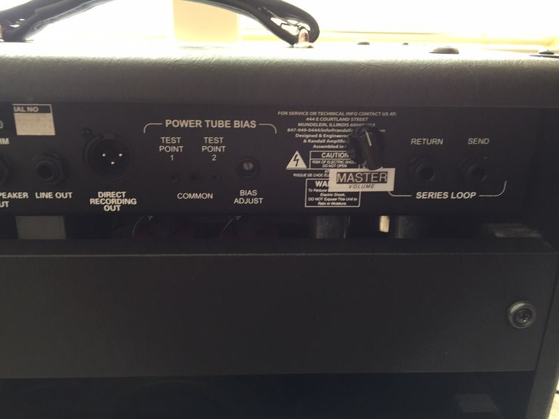
Master volume mod:
- lift the right side (looking from the front) of C9 from the board;
- solder to pin 1 of an A1M pot (1M log / audio taper) pot;
- solder an 0.1uF cap from pin 2 of the pot back to the vacant hole from C9;
- ground pin 3 of the pot (a convenient ground point is the ground pin at R20;
- drill a hole in the back of the head for the master volume pot (somewhere around the serial number is a good location). Alternatively, on one of my amps I've relocated the boost pot up a little and put the master volume below it so its on the front of the amp. Relocating the boost pot does involve cutting the PCB though.
Explanation: we're basically bleeding signal to ground before it goes to the power amp.
Switchable density:
The RM20's come with different values on the density PCB to whats in the RM100s. Changing to the RM100 values makes for a noticeable improvement. Basically change C3 out to a 100uF 100V electrolytic cap. While you're doing this, you can make the density control switchable by fitting a switch to the + lead of C3. With the switch open, the density control is disabled and the amp is far less stiff (you're basically turning off the NFB) but the power section will distort alot easier and its response becomes far less linear. I like both settings depending on what I'm playing. I'd also recommend fitting a small value cap across C3 and its + on the PCB to block DC and provide some attenuation for high frequencies. Something around the 500pF is good. I used a 470pf cap.

